What 'Wrong Laser Cleaning' Looks Like on a Critical Aircraft Part

What you're looking at
The image above is a frame from a marketing video by Laser Photonics, a competing laser-cleaning vendor. We're not posting it to attack — we're posting it because the surface condition of the part shown in their own footage is exactly the kind of result that should never appear on a critical aircraft component, and because the issue is visible to the naked eye.
The part is a turbine blade — likely from a gas turbine (the visible "SIEMENS" stamp suggests a Siemens unit, possibly a power-generation turbine, though the same blade types appear in regional aviation engines). What matters is the airfoil surface: the cross-hatched, almost diamond-pattern texture running across the curved span. That texture wasn't there before cleaning. The laser put it there.
We asked an AI to look at it cold
We took the same image and asked Google Gemini to evaluate it without telling the model our position or who made the video. We wanted to see whether a generalist AI looking at the part would flag the same issues an FAA-trained A&P inspector would flag. It did, immediately. Gemini's analysis broke down into three specific concerns — and they're worth walking through in detail because they cover exactly what makes the difference between safe laser cleaning and unsafe laser cleaning.
1. Heat-Affected Zone (HAZ) — the invisible damage
Turbine blades are made from specialized superalloys — Inconel 718, CMSX-4, René N5 — engineered for extreme temperature and centrifugal stress. They are not standard stainless steel. The crystallographic grain structure of these alloys is part of why they survive the hot section of a turbine; some single-crystal blades have no grain boundaries at all by design.
Laser cleaning works through ablation — vaporizing surface contaminants in nanoseconds before heat has time to thermalize into the substrate. That's the principle. But it only works if the laser parameters (pulse duration, peak power, repetition rate, scan speed) are tuned to the specific contaminant and substrate combination. Get the parameters wrong and the energy bleeds into the metal. The grain structure changes. Recrystallization can occur. A "recast layer" forms where the metal melted briefly and resolidified — and that recast layer is brittle, has different thermal expansion than the parent alloy, and is prone to cracking under operational stress.
The visible surface texture in the video frame is a strong indicator that thermal energy reached the substrate. Proper laser cleaning leaves no visible substrate texture change — only the contaminant should change state.
2. Surface roughness and stress risers
The mottled, pitted appearance on the airfoil isn't just cosmetic. In aviation, surface finish on rotating components is a critical engineering parameter. Two reasons:
- Fatigue life: Smooth surfaces resist fatigue cracking; rough surfaces concentrate stress at every microscopic peak and valley. Each one of those laser striations is a potential crack-initiation site under cyclic loading. On a turbine blade rotating at 10,000+ RPM in 1,400°C exhaust, you do not want crack initiation sites you didn't design in.
- Aerodynamics: Compressor and turbine blades are precision-machined to control airflow. Surface texture changes — even at the micrometer scale — alter boundary-layer behavior, change heat-transfer coefficients, and degrade engine efficiency. The whole point of cleaning a blade is to restore its as-designed surface, not to add a new texture.
If you can feel those marks with a fingernail, the part's surface roughness Ra (roughness average) has been pushed outside the manufacturer's specification — and the part may already be out of tolerance for return to service.
3. FAA / OEM compliance — the regulatory reality
From a regulatory standpoint, cleaning a turbine blade is a maintenance process. That means three things have to be true before the part can fly again:
- Approved data: The cleaning method must be listed in the engine manufacturer's Component Maintenance Manual (CMM) or in approved Standard Practices. If laser cleaning isn't explicitly listed for that part, using it without an Alternative Method of Compliance (AMOC) approval can void the part's airworthiness.
- No removal of base metal: Most aviation cleaning standards specify that cleaning must not remove parent material. If the laser is etching into the substrate (which is what those marks visually suggest), the part has lost dimensional integrity.
- Documented process control: The exact laser parameters used must be repeatable and recorded — power, pulse duration, frequency, scan speed, fluence, max substrate temperature. Without this, a Designated Engineering Representative (DER) cannot sign off the work.
None of this is hypothetical. The FAA's Advisory Circular AC 43.13-1B is explicit: any maintenance method must be "equal to or superior to the methods listed." Visible substrate damage isn't equal-to-or-superior to anything.
4. Rotational balance — the issue that scales with every blade
Here's a concern that doesn't show up on a single-part inspection but absolutely shows up on the engine: balance. A turbofan engine has dozens of blades per stage and multiple stages — a single low-pressure turbine module can carry 60 to 80 blades, all spinning together at 8,000 to 14,000 RPM. Those blades are precision-balanced as a set when the rotor is built. The OEM moment-weighs each blade, sorts them, and arranges them around the disk so that mass is symmetrically distributed about the rotational axis.
Now imagine the laser removes a few grams of metal asymmetrically from each blade — different amounts from different blades depending on where the contamination was, how long the laser dwelled, and whether the operator was rushing the last few. You've just turned a balanced rotor into an unbalanced one.
The consequences scale fast with RPM (vibration force grows with the square of rotational speed):
- Bearing wear: Imbalance generates a synchronous vibration at 1× rotor speed. Bearings designed for balanced loads see accelerated wear, shortened service life, and elevated oil temperatures.
- Cyclic blade loading: Imbalance also induces vibration in the blades themselves — bending modes that they weren't designed to see continuously. This accelerates fatigue crack growth in the very components that are hardest to inspect.
- Engine mount stress: The vibration transmits through the mount structure into the airframe. On large engines, milligrams of imbalance per blade summed across all stages can produce engine-mount loads measured in hundreds of pounds of cyclic force.
- Catastrophic case: Severe imbalance contributes to blade liberation events — when a fatigue crack initiated by the vibration finally propagates to failure, the released blade can damage adjacent blades and, in the worst documented cases, breach the engine case.
This is why every blade rebuild includes a moment-weighing step, and why some shops require post-cleaning weight verification before a blade goes back into the disk. If the cleaning method removes parent material — even at the microgram level — you have to re-verify balance class. If the cleaning method is consistent and removes only contaminants (which is the entire point of selective ablation), the original balance class is preserved.
Visible surface texturing like the marks in the image at the top of this post strongly suggests material removal beyond what the contamination accounts for. On a single static part, that might be tolerable. On 60 blades of a low-pressure turbine module spinning at 12,000 RPM, the cumulative imbalance is exactly the kind of latent defect that turns into a vibration warning at 200 hours of service and a real problem at 800.
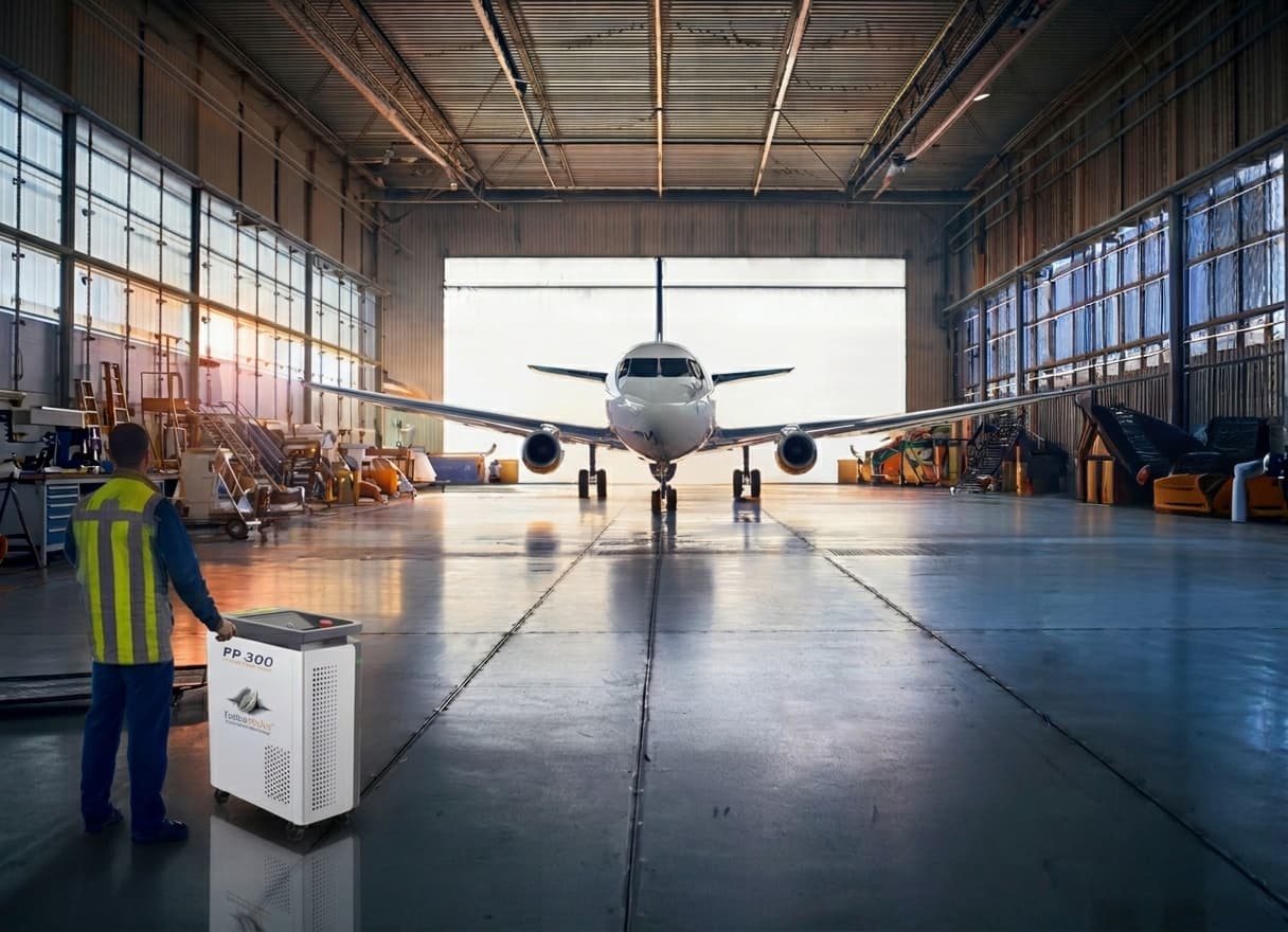
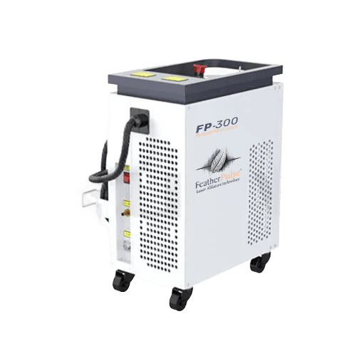
What proper laser cleaning is supposed to look like
The FP-300 FeatherPulse system was independently evaluated by Textron Aviation's Materials & Processing Engineering group. The test condition was the most aggressive case: full paint ablation on thin alclad-aluminum aircraft skin. Cross-sectional microscopy after cleaning showed:
- Alclad layer fully intact (zero observable damage)
- Substrate thickness measured at 0.0022 in — within original spec tolerance
- No heat-affected zone (no thermal discoloration, no grain structure changes at the ablation boundary)
That's the threshold a critical-aircraft-parts laser-cleaning system has to clear. Bare metal, identical to the as-machined surface, with zero substrate texture or thermal signature. If you can see the laser's path on the metal, the laser was wrong for the job.
The selectivity that makes safe cleaning possible
Proper laser cleaning at 1064 nm exploits a fundamental absorption asymmetry: paint, oxide scale, CMAS glass, and combustion residues absorb 85–95% of the laser energy at this wavelength. Polished nickel-superalloy substrates reflect 65–75% of the same energy. That asymmetry is the safety margin — the same beam that vaporizes contaminants warms the substrate by only tens of degrees per pulse.
The asymmetry only protects you if you operate in the right window. Above the substrate's ablation threshold (typically >25 J/cm² for clean nickel superalloys), the safety margin disappears and the substrate starts to absorb enough energy to melt or recrystallize. A 300 W pulsed fiber system tuned to 5–8 J/cm² stays comfortably below that threshold. A continuous-wave (CW) high-power system, or a pulsed system run at the wrong pulse duration, can blow right through it.
What inspectors should look for after laser cleaning
If you're evaluating a laser-cleaned part for return to service, these are the non-negotiables. They apply to any laser-cleaning vendor, including ours.
Visual inspection (the easy one)
- The cleaned surface should match the as-machined or as-coated finish — no new texture, no mottling, no striations
- Color should be correct: bare metal looks like bare metal; TBC ceramic looks like TBC ceramic
- No discoloration at the cleaning-pattern boundaries (a faint gold or blue tint at the edges of a scan path is a heat signature)
Fluorescent Penetrant Inspection (FPI)
- The aviation gold-standard NDT for turbine blades
- Will reveal any micro-cracks too small to see with the naked eye
- Should be performed after laser cleaning before the part is released for service
Surface profilometry
- Measure surface roughness (Ra) and compare against the OEM specification for that part
- Compare pre-cleaning and post-cleaning Ra to confirm no roughening occurred
- For aviation primer adhesion, target Ra is typically 0.8–1.6 μm — a window that proper laser cleaning achieves naturally
Eddy-current or ultrasonic thickness
- Verify that < 2% substrate material has been removed
- For TBC-coated blades, also verify TBC thickness has not been reduced beyond spec
Moment-weighing (for balanced rotor sets)
- Re-weigh each cleaned blade on a moment-weight scale calibrated for that rotor stage
- Compare against the as-built moment-class for the part — if the cleaning has shifted the blade out of class, it has to be re-sorted into the rotor or replaced
- For HPT and LPT modules, the OEM CMM specifies the allowable moment-weight tolerance per stage; this is non-negotiable for return to service
The Component Maintenance Manual check
- Open the CMM for the specific part
- If laser cleaning is not listed as an approved method, you need an AMOC before the part can fly
- If the CMM specifies chemical or ultrasonic cleaning, switching to laser is a "major process change" requiring engineering substantiation
The bottom line
Laser cleaning is the right tool for a wide range of aviation surface-prep jobs — when the laser, the parameters, and the operator are matched to the substrate and the contaminant. It is the wrong tool when generic settings, untuned power, or the wrong pulse architecture are applied to a high-value rotating component. The image at the top of this post is what "wrong tool" looks like on the surface of a critical part.
If you're considering a laser-cleaning vendor for any aviation work — whether that's an FP-300 from Aviation Laser Services, a robotic cell from SPARCL, or any other vendor — ask three questions before you sign anything:
- Show me independent third-party microscopy proving zero substrate damage on a representative substrate. (We use the Textron Aviation alclad-aluminum cross-section.)
- Show me your process specification — the exact power, pulse duration, frequency, scan speed, and fluence, with documented operating envelopes. ("We dial it in by feel" is not a process spec.)
- Show me your inspection protocol after cleaning. (FPI, profilometry, thickness measurement — and an actual report, not just "we look at it.")
If a vendor cannot answer all three, the cost of laser cleaning isn't measured in machine purchase price — it's measured in the hours of NDT that has to follow every cleaning cycle, and in the parts that may have to be scrapped because the cleaning damaged them.
Get those answers before the laser hits the metal, not after.